Findings: Many Japanese vehicles of this vintage flip the polarity on their headlights. A +12 volts is sustained to the headlamp while ground is applied to the low-beam and high-beam prongs for activation. It is not a simple wire swap but requires a Negative Switched Conversion box. The one I bought was messy. You connect one vehicle H4 connector to the conversion box and then stretch an H4 cable to each non-Japanese headlamp. This puts the power load for two headlamps on to the wiring of a single headlamp plus a little more power loss for the conversion. I returned it to Amazon and will continue my search for a better solution.
Why did the old incandescent lamp work with negative switched wiring? The old lamp use a filament. Run 12 volts DC through it in any polarity and it will heat it up the filament and produce light. New LED lamps require specific polarity.
Volt Meter Testing With Jumpers
| Lamp State | +12 volts | -Ground |
|---|---|---|
| Low Beam | Blue | Red |
| Low Beam | Black | Red |
| High Beam | Black | Blue |
| High Beam | Red | Blue |
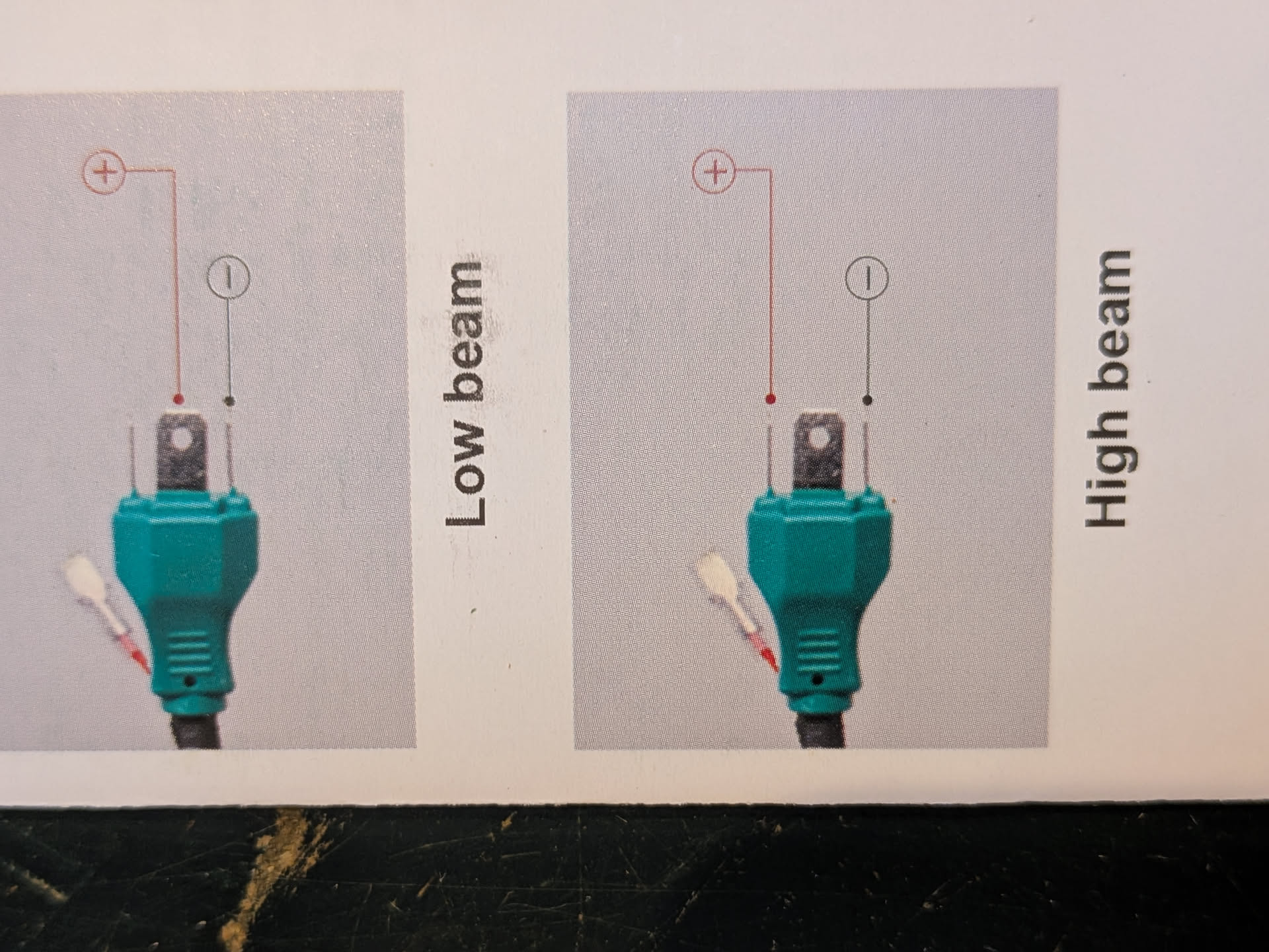
When Low Beam is on Red is ground and Blue or Black are +12 volts.
When High Beam is on Blue is grould and Black or Red are +12 volts.
Using at 12 volt supply, I can put +12 on the right (shown as I ) prong, and use the center prong to get low beam and the left prong to be High beam.
This means a simple cable swap will not work, and a capacitor based control box is required to complete the upgrade.
